November 2, 2026 · Indumor
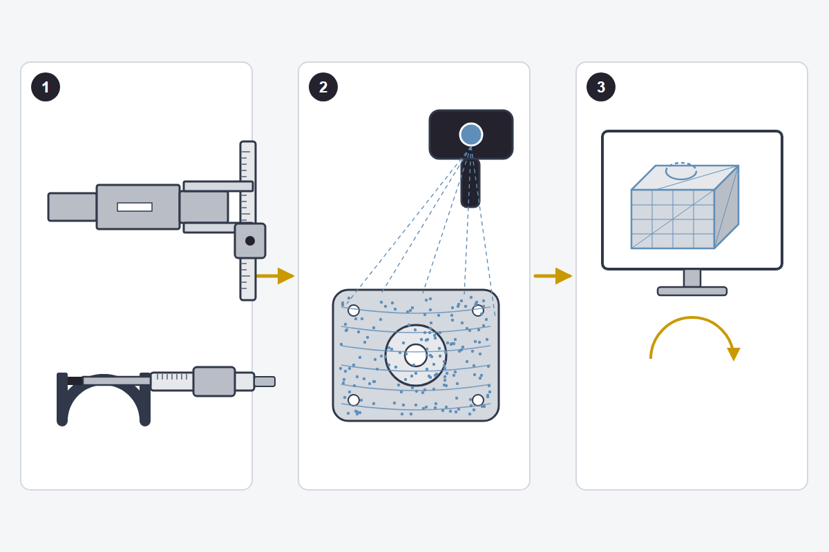
1 Caliper and micrometer · 2 3D scanner and point cloud · 3 CAD model.
It is seven in the morning at an animal feed plant and the pellet mill is open on the floor, with the die outside, the rollers on a pallet and the gearbox still hanging from the crane. Two people from the shop walk around it with a caliper, a tape, a graph-paper notebook and a phone that will not stop taking pictures. In three hours the machine has to be back together, and in those three hours they have to take away everything needed to build the next one. That is a survey, and the question that always comes up is which tool to do it with.
On paper. A tape measure for lengths, a caliper reading to 0.02 mm for diameters and thicknesses, a 0.01 mm micrometer wherever there is a fit, a protractor for angles, a dial indicator on a magnetic base for runout, radius and thread gauges, and a precision level. With that kit, which fits in one box, any machined part can be surveyed.
With the part in hand. What the manual does not say is the order. First you measure in position, before taking anything apart, the clearance between shaft and bushing, the alignment of the pulleys, the center distance. Those numbers vanish the moment the first bolt is loosened. Then, with each part loose, the dimensioned sketch is made right there, not the next day, and every photo has something for scale next to it, a ruler or the caliper opened to a known size. A sketch without dimensions is, a week later, just a picture.
On paper. A structured-light or handheld laser scanner sweeps the part and returns a cloud of millions of points that becomes a triangle mesh, an STL file. Typical accuracy runs from hundredths to tenths of a millimeter depending on the device. It is made for housings, pump bodies, impeller blades, any curved surface that would come out wrong with a caliper.
With the part in hand. The mesh is not a drawing. An STL is a shell of triangles; to build anything you have to model it in CAD on top, rebuilding cylinders, planes and holes with round numbers and tolerances. That engineering usually takes more hours than the scan itself. Shiny or black surfaces scan badly, so they get a developer spray that later has to be cleaned off. It is no walk in the park. For a shaft or a sprocket the scanner is an unnecessary luxury and the micrometer wins by a mile.
On paper. For a six-meter hopper, a structure or the layout of an entire plant, photogrammetry builds a model from hundreds of photos taken around the object, and a total station or a laser tracker measures points tens of meters away with millimeter accuracy.
With the part in hand. In a plant, what gets used most is still the 30 m tape, the laser distance meter and plenty of photos. The total station shows up when the foundations of a line with many aligned machines have to be replicated, and there it earns every dollar.
Everything ends in the same place, a 3D model, an assembly drawing, part drawings with their tolerances and a bill of materials with the steel and the heat treatment of each one. That documentation is what goes into the shop and what you keep for the next spare. How a worn part is measured without copying the wear is in spare parts without drawings, and the whole process, from the goal to the tested copy, in how a machine gets copied.
In one sentence: caliper and micrometer for machined parts, scanner for curved ones, total station for big ones, and everything measured in position before taking it apart. When there is a machine to survey, at Indumor we show up with the right tools and come back with the drawings; the service is described in industrial reverse engineering.
Tell us what it is and where: we go with caliper, scanner or total station and come back with the drawings.
© Indumor 2010–2026 — Industrial steel fabrication, Córdoba, Argentina
